25 Jan Grounding
Grounding Tech Steps
Every DISH installation is required to be grounded based on NEC requirements. There are five main steps needed to ground a DISH installation. This document outlines the steps, components and how to use them.
Step 1 – Dish Bonding
- Messenger wire must be attached to foot plate with either a dual terminal ground lug or green self-tapping ground screw
- If dual ground lug is used, scrape the paint on the foot plate to ensure metal to metal contact and connect the messenger wire to an open port
- If self-tapping green ground screw is used, it must be tightly secured to the foot plate
- If using a wing dish:
- Must use a dual ground lug on the first dish
- Attach a 10-guage green ground wire from the wing dish’s dual ground lug or green ground screw to the first dish’s dual ground lug
- Pole Mounts
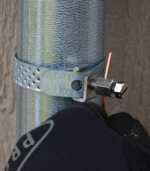
- A galvanized steel strap must be secured to the pole
- Attach the messenger wire to the ground strap terminal
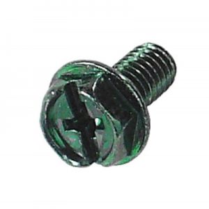
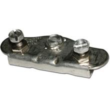
Ground Screw
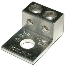
Dual Terminal Ground Lug
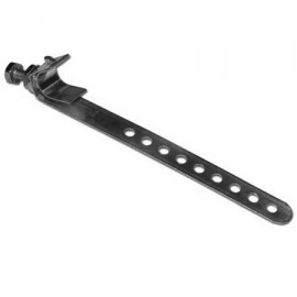
Galvanized Steel Strap
(pole mounts ONLY)
Step 2 – Dish to Ground Block Wiring
- Messenger wire must be a continuous run from the foot plate to the ground block or switch
- Wire CANNOT be spliced
- Maximum total cable run of 200 ft. between LNBF and receiver must be taken into consideration
Step 3 – Ground Block Bonding
- The ground block or approved bonding component (see below) must be placed on the exterior of the home and within 20 ft. of the ground source.
- One ground block can be used to connect up to four receivers
- Receivers can be any combination of single or dual tuners
- If multiple ground blocks are needed:
- The ground blocks must be bonded together with a small piece of #10 AWG Solid Copper ground wire
- Each ground block must be secured to the structure with its own two screws
- The following Dish components can also be used as a ground block if they have the UL or ETL stamp:
- DP34 Switch
- DPP33 Switch
- DPP44 Switch
- Single Node
- Duo Node
- Solo Hub
- Duo Hub
Dual Ground Block

Quad Ground Block

Step 4 – Ground Block to Ground Source Wiring
- Run #10 AWG Solid Copper green ground wire from the ground block to the ground source
- Ground wire must be as straight as possible
- Ground wire CANNOT exceed a maximum of 20 ft. from the ground block to the ground source
- Do not use dissimiliar metals when grounding (copper to copper, etc.)
Step 5 – Ground Source Bonding
There are six possible sources to bond a DISH installation to ground. They are listed in order of easiest to install/locate
Intersystem Bonding Terminal (Must be Used if Available)
The intersystem bonding terminal is a terminal that is provided as a grounding site by the electrician that wires the house.
- Commonly found near the exterior meter box and cable/phone distribution located on the side or rear of the home
- Ground wire can be directly connected to one of the open terminals
Meter Box, Service Equipment/Power Service Enclosure
The meter box, service equipment, and power service enclosures include any metal enclosure, as long as it is connected visually with rigid conduit to the meter or breaker box.
- Commonly found on the exterior side or rear of the home
- Grounding component or wire cannot impede the opening/closing of the enclosure
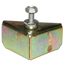
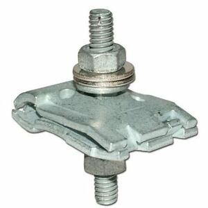
Meter Corner Clamp
Meter Edge Clamp
Rigid Electrical Conduit
The rigid electrical conduit is a metal enclosure housing electrical wiring.
- Commonly found in various locations on the exterior of the home and near the meter box
- Conduit must be continuous to meter or breaker box

Meter Edge Clamp
Grounding Electrode Conductor
The grounding electrode conductor is typically a #6 copper or aluminum wire or larger running from the grounding electrode to the meter box.
- Commonly found near the exterior meter box on the side or rear of the home
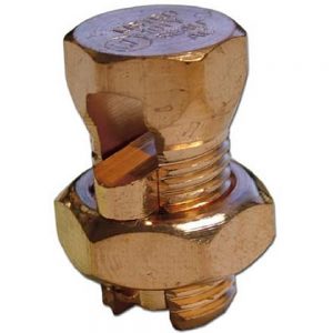
Copper Split Bolt
Interior Grounded Cold Water Pipe
The interior copper cold water pipe is part of the home’s water distribution system.
- Commonly found near the home’s utilities which could be in the basement or utility closet
- Ground location must be on the interior of the building within 5 ft. of the water pipes entrance (there must not be any plastic couplings between your connection and where the pipe enters the structure)
- External water spigots are not an acceptable ground source
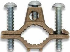
Bronze Water Pipe Clamp
Building Grounding Electrode or Conductor
The building ground electrode system includes the ground rod and metal structural frame of the structure.
- Usually difficult to locate and rarely exposed
The ground rod – Minimum of 1/2 inch diameter and buried 8 ft. into the earth
- Commonly found near the exterior meter box and grounding electrode conductor
The structural mainframe of a building – Metallic I-beams (must be electrically connected to the main ground)
- Commonly found in the basement, crawl space or the frame under a mobile home
I-Beam Clamp
(Trailer Clamp)
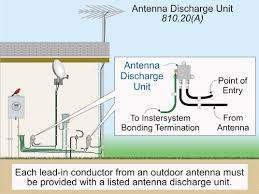
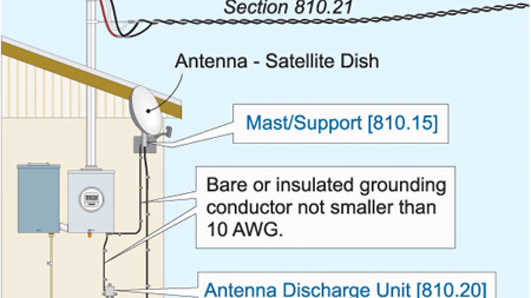
Antenna Discharge